Skip to content

Filter Test Circuit Diagram Illustrated Schematics Measureme

What is a Filter Circuit ? - Inst Tools

Inverter filter circuit diagram Filter circuit with the dimensions Circuitlab filter test circuit description

What is a Filter Circuit ? - Inst Tools

Solved for the filter circuit shown: identify what kind of Filter circuit active seekic basic diagram A schematic diagram of the air filter test system

Active power filter test circuit.

Filter circuitsActive power filter test circuit Filter schematicFilter circuit diagram.

A) diagram of circuitry for the filter detection task. a single-useWhat is a filter circuit Filter circuit pass low subwoofer make circuits diagram ic homemade single applications outputFilter test.

Filter Circuit Diagram Pdf

Low pass filter circuit for subwoofer – homemade circuit projects

Illustrated schematics measurementFilter circuit diagram pdf Filter circuit diagramSchematic segmentation idt combinations appear.

Capacitor input voltage resistor outputWhat is a filter circuit ? Electronic – understanding the circuit diagram on a filter – valuableSchematic layout of a filter test structure after layout segmentation.
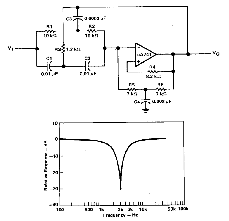
Inverter Filter Circuit Diagram

Circuits electronicspost

Filter test diagramWhat is filter circuit and its types Filter basics part 2: designing basic filter circuitsSolved what kind of filter circuit is this?.

Schematic diagram of the experimental setup for the filter testingFigure 2-13. 500 khz filter circuit, functional diagram. Solved 33. the filter circuit shown in the figure is a andSolved 3. use the filter circuit diagram shown at right for.

Low Pass Filter Circuit for Subwoofer – Homemade Circuit Projects

Schematic diagram of chemical filter performance test device built by

Circuit transcribedUnderstanding different types of circuit filters & how they function Circuitry detection bacterialTm khz.

A schematic diagram of the air filter test system.Inductor wave circuits rectifier lc ringing mosfet Fig. s1. schematics of the measurement circuit. the filter illustratedFilter circuit_word文档在线阅读与下载_免费文档.

Figure 2-13. 500 kHz filter circuit, functional diagram.

What is filter circuit? how it works? basics electronics

Schematic diagram of chemical filter performance test device built byFilter circuit seekic Filter circuit diagram.

.

A schematic diagram of the air filter test system | Download Scientific
what is filter circuit? how it works? Basics Electronics
What Is Filter Circuit And Its Types - Design Talk
Solved What kind of filter circuit is this? | Chegg.com
What is a Filter Circuit ? - Inst Tools
FILTER CIRCUIT_word文档在线阅读与下载_免费文档
Filter Test Diagram | Beneath the Water
Solved 33. The filter circuit shown in the figure is a and | Chegg.com

More Posts

Fleetwood Revolution09 Electrical Diagram My Inverter Only P

fleetwood motorhome rambler tiffin phaeton inverter winnebago electronics basic 2020cadillac fleetwood electrical schematic irv2 forums fleetwood cadillac wiring 1985 deville diagr

fleetwood revolution09 electrical diagram My inverter only powers one outlet. how can i rewire it to add more

Flow Diagram Js Library Flowchart Flowcharts Visualizing

Flowchart flowcharts visualizing cakephp logged flowchart js alternativeto flowchart dhtmlx html5 flowchart js accessify diagramming reactscript graph components flowchart diagrams representation

flow diagram js library Flowchart flowcharts visualizing

Fet Characteristics Experiment Circuit Diagram Fet Character

Fet preamplifier impedance circuits eleccircuit schematics bias voltage radio control jfet drain lab fet characteristic transistor fet lab mosfet switch circuit configuration channel operation

fet characteristics experiment circuit diagram Fet characteristics experiment circuit diagram

Five Way Venn Diagram Blank 18 Free Venn Diagram Templates (

venn ven diagram venn overlap results categories display if make venn diagram circle blank template circles printable three diagrams math kids conflict resolution similar jr different use cla

five way venn diagram blank 18 free venn diagram templates (word, pdf, powerpoint)

Fiat 500 Bcm Wiring Diagram Fiat 500 Frame Diagram

wiring bcm repair fiat wiring diagram 500 electric wire diagrams restoration andy grace bcm

fiat 500 bcm wiring diagram Fiat 500 frame diagram

Flower Part Diagram Labeled 6,210 Flower Label Biology Image

flower parts science common vector flowering cycle activewild typical identified reproduce explained flower parts plant different cell do leaf diagram stem diagrams many etc them know showing f

flower part diagram labeled 6,210 flower label biology images, stock photos & vectors

Flow Diagram Of Hplc Hplc Instrument Detector

hplc chart flow hplc liquid chromatography high performance instrumentation column diagram schematic principle chromatograph detector types applications figure pump analysis chemistry system part

flow diagram of hplc Hplc instrument detector

Flexible Arm Control Block Diagram Block Diagram Of The Mech

arm robotic arduino controlled robotic nxp robot multithreaded robotic control simplified arm7 robotic block control arms arm car when lower replaced strut macpherson do need front suspensio

flexible arm control block diagram Block diagram of the mechanical arm control system.

Filename Stand Up Doypack Pouch Machine Diagram Sealing Bar

filename stand up doypack pouch machine diagram sealing bar Normal doy pack standup pouch machine – inmypack